
Thermal Pads: Selection Guide for EV, ESS & Power Electronics
Pre-cured gap pads with electrically insulating options for repeatable, clean thermal assembly
Values shown are indicative portfolio references only. Grade-specific values vary with filler package, thickness, compression, surface condition, reinforcement, adhesive option and measurement method, and should be confirmed by the product TDS.
Thermal pads are pre-cured, soft thermally conductive sheets, typically available with electrically insulating options, that help transfer heat from a component to a heat sink, cold plate or housing. Because they are supplied as die-cut, fixed-thickness parts, they offer clean handling, repeatable assembly and good reworkability. This makes them useful across EV battery, ESS and power electronics designs where the gap is defined, the assembly pressure is controlled and electrical insulation may be required.
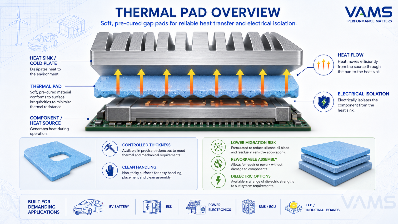
Thermal pad overview — die-cut soft conductive sheet between component and heat sink.
What a Thermal Pad Is
A thermal pad is a thermally conductive elastomer sheet, commonly silicone-based and filled with ceramic or other thermal fillers. It is supplied at a defined thickness and can be die-cut to the required shape. Compared with dispensable gap fillers, a pad is a solid part that can be placed and compressed during assembly. Compared with grease, thermal pads offer controlled thickness, cleaner handling and lower migration risk, while many grades also provide dielectric isolation. The trade-off is usually a thicker bond line and the need to control compression.
- Heat transfer: fills the air gap between component and heat sink with a conductive path
- Electrical isolation (options): many grades keep the component dielectrically separated from the sink
- Clean handling: die-cut parts with optional liners for repeatable, fast assembly
- Lower migration risk: solid pads generally have lower pump-out risk than grease, but compression set, creep and edge extrusion should still be validated under thermal cycling and vibration
Pad vs Gap Filler vs Grease
Thermal pads are one part of the broader TIM family. The right choice depends on whether the interface has a fixed gap, a variable gap, a thin flat bond line or a need for automated dispensing.
| Interface Type | Best For | Main Advantages | Key Limitations |
|---|---|---|---|
| Thermal Pad | Fixed gaps, clean assembly and reworkable interfaces | Die-cut format, controlled thickness, clean handling, dielectric options | Requires compression; less suitable for highly variable gaps |
| Dispensable Gap Filler | Variable gaps, large-area EV battery cooling and automated dispensing | Excellent gap tolerance, low-stress filling, good process automation | Requires dispensing equipment, mixing/curing control and process validation |
| Thermal Grease / Paste | Very thin, flat, high-power interfaces | Very low bond-line resistance when properly applied | Requires mechanical fastening; pump-out and dry-out must be validated |
For a broader overview of TIM families, see the Thermal Interface Materials guide. For variable-gap battery cooling designs, see the thermal gap filler guide.
Construction & Options
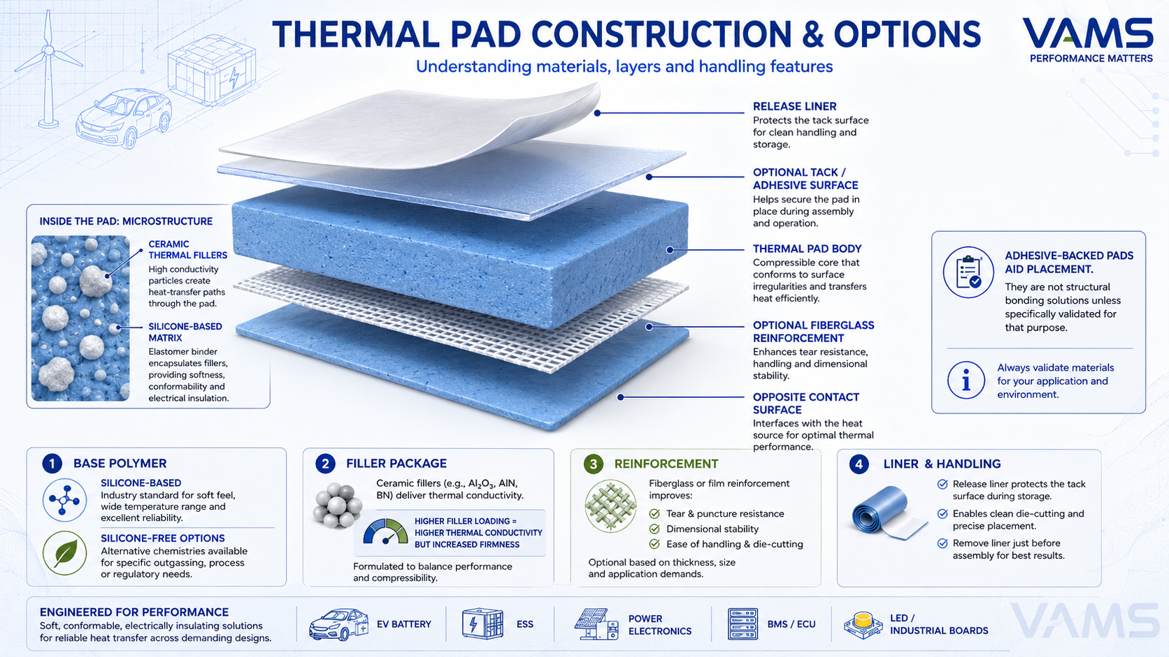
Thermal pad construction — base polymer, thermal filler, reinforcement, tack/adhesive and liner.
Thermal pads can be tailored across several construction choices, each affecting thermal performance, handling and assembly stress.
Matrix / base polymer
Silicone-based pads are widely used because they offer softness, temperature resistance and good surface conformity. Silicone-free options may be selected for applications with silicone contamination, LABS or optical/sensor sensitivity concerns.
Thermal filler package
Ceramic or other thermally conductive fillers provide the heat path through the pad. Higher filler loading can improve conductivity, but may also increase hardness, density, cost and compression force.
Reinforcement
Fiberglass or film reinforcement can improve handling, die-cut stability, tear resistance and puncture resistance, especially for large or thin pads. However, reinforcement may reduce conformity compared with non-reinforced soft pads.
Surface tack / adhesive
Light tack or adhesive on one or both sides can support placement and assembly. It should not be treated as structural bonding unless the material is specifically designed and validated for that purpose.
Liner / release film
Protective liners keep the pad surface clean and support manual or automated placement. Liner design should match the assembly sequence to avoid contamination, misalignment or trapped air.
Key Properties
| Property | Standard / Method | Why It Matters |
|---|---|---|
| Thermal conductivity (k) | ISO 22007 / ASTM D5470 | Bulk heat conduction capability (W/m·K) |
| Thermal impedance | ASTM D5470 | Practical interface performance under defined pressure and thickness |
| Thickness | — | Defines gap-fill capability; thinner lowers resistance |
| Hardness | Shore 00 / OO | Softer pads conform better and apply less stress |
| Compression / deflection | ASTM D575 or internal method | Assembly stress on cells, PCBs and ceramic substrates |
| Dielectric strength | IEC 60243 / ASTM D149 | Electrical isolation between component and sink |
| Flame rating | UL 94 | Important for EV battery, ESS and power electronics safety |
| Thickness tolerance | Drawing specification / internal method | Affects final gap, compression percentage and thermal impedance |
| Compression set / stress relaxation | ASTM D395 or internal aging method | Indicates long-term thickness recovery and pressure retention |
| Tensile / tear strength | ASTM D412 / ASTM D624 | Important for handling large, thin or complex die-cut pads |
| Tack / adhesive strength | Internal method | Helps placement, but not structural bonding unless validated |
| Volume resistivity | IEC 62631 / ASTM D257 | Supports electrical insulation assessment |
| Operating temperature | — | Continuous service range, grade dependent |
Indicative methods and ranges across product grades. Grade-specific values should be confirmed by the product TDS.
Selection Guide
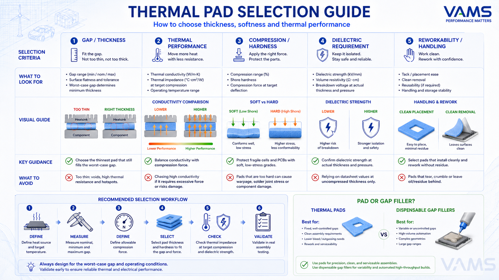
Selection matrix: thermal pad by gap/thickness, conductivity, hardness, dielectric and reworkability.
Selection workflow
- Define the heat source, power loss and target temperature
- Measure nominal, minimum and maximum interface gap
- Define allowable compression force or stress on the component
- Select pad thickness, hardness and compression range
- Check thermal impedance, dielectric strength and flame rating
- Confirm handling needs such as liner, reinforcement, adhesive side and die-cut geometry
- Validate with real assembly testing, thermal cycling and vibration
- Set thickness to the real gap: choose the thinnest pad that still fills the worst-case gap, since impedance rises with thickness
- Match conductivity to heat load: higher k helps, but balance it against hardness, cost and compression force
- Protect fragile parts: choose soft, low-deflection grades over cells, ceramic substrates and thin PCBs
- Confirm dielectric: verify breakdown voltage at the working thickness and pressure
- Consider handling: reinforced or lined pads for automated assembly and large areas
Compression-driven performance
Thermal pad performance depends strongly on compression. A pad that is too thick or too hard may increase assembly force and stress fragile components, while a pad that is too thin may not contact both surfaces across tolerance stack-up. The best design defines the nominal gap, worst-case gap, target compression and maximum allowable stress before selecting thickness and hardness.
Thermal pads suit fixed gaps, clean manual or pick-and-place assembly, and designs that require reworkability. Dispensable gap fillers are usually better for variable gaps, large-area battery cooling and automated high-volume production. Grease or PCM may be better for very thin, flat, high-power interfaces. The final choice should be based on gap tolerance, compression limit, thermal impedance target and production process.
Applications
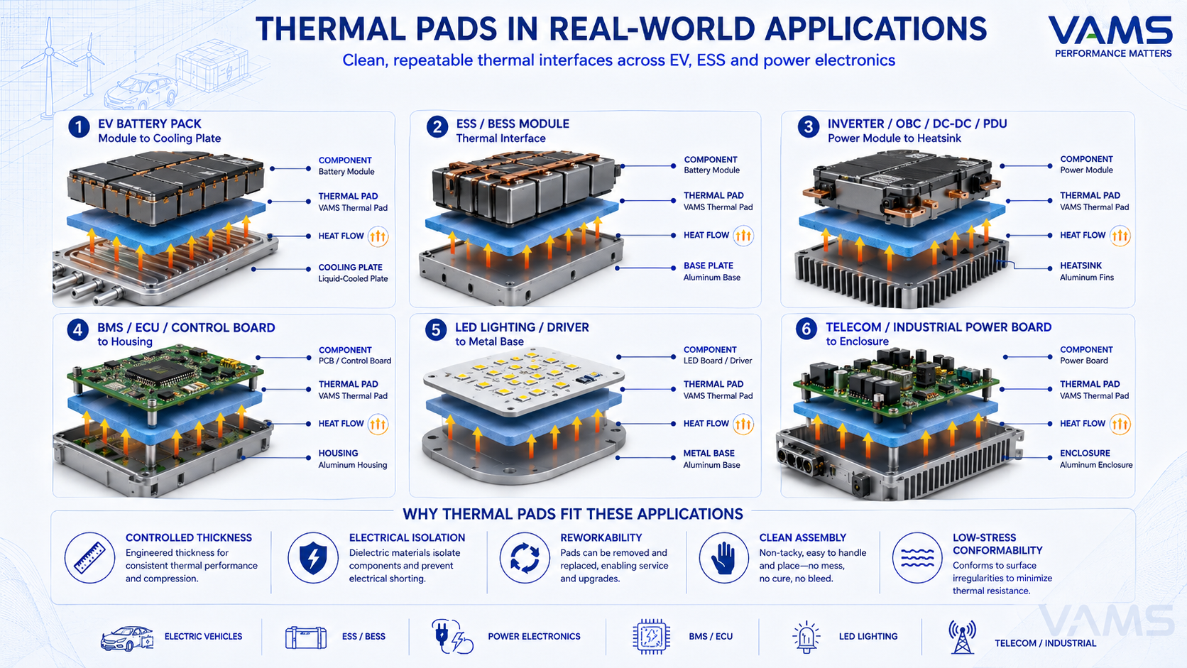
Applications montage: EV battery module, power module / inverter, BMS/ECU, LED, ESS and telecom boards.
EV battery packs
Thermal pads can be used between modules, cell carriers, cooling plates or enclosure surfaces when the gap is defined and repeatable. Soft, low-stress grades are preferred to reduce mechanical load on cells, while dielectric strength and flame rating should be confirmed according to battery safety requirements.
ESS / BESS modules
Thermal pads support module-to-cooling-structure interfaces, enclosure thermal transfer and power-conversion cooling where serviceability and clean assembly are important.
Inverter / OBC / DC-DC / PDU
Thermal pads support heat transfer from power modules, MOSFETs, IGBTs or SiC devices to heat sinks or cold plates, especially where electrical insulation and reworkability are required.
BMS / ECU / control boards
Pads can transfer heat from ICs, processors, transformers or power components to housings, frames or local heat spreaders while limiting mechanical stress on the PCB.
LED and lighting modules
Thermal pads help transfer heat from LED boards and drivers to aluminum housings or heat sinks while simplifying assembly.
Telecom and industrial boards
Pads are used between RF power devices, PSUs, embedded boards and enclosures where defined thickness and electrical isolation are required.
Design & Process Notes
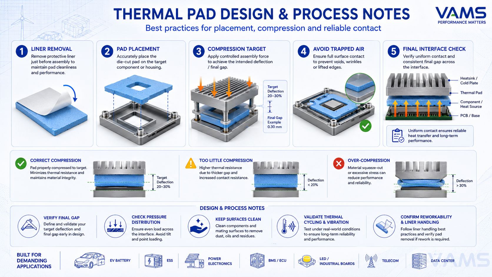
Process detail: pad placement, compression to target deflection, liner removal and avoiding trapped air.
- Compression target: impedance is rated at a given compression — define assembly force and final gap
- Avoid over-compression: excessive deflection raises stress on cells and substrates and can damage parts
- Mind tolerance stack-up: if the real gap varies a lot, a fixed-thickness pad may not fully contact — consider a gap filler instead
- Air entrapment: place to avoid trapped air pockets that reduce contact area
- Reworkability: many pads can be removed and replaced during service, but adhesive-backed or highly tacky options should be validated for residue and removal behavior
- Handling: use reinforced or lined grades for thin or large pads and automated lines
- Verify final gap: confirm the compressed pad thickness after assembly, not only the nominal pad thickness
- Check pressure distribution: large pads may not compress uniformly if the heat sink, battery module or housing is not flat
- Control placement tolerance: pad misalignment can reduce heat-transfer area or create local stress
- Clean contact surfaces: dust, oil or release-film residue can reduce wet-out and increase contact resistance
- Validate aging: check thermal cycling, humidity, vibration and compression set under real operating conditions
Common Thermal Pad Selection Mistakes
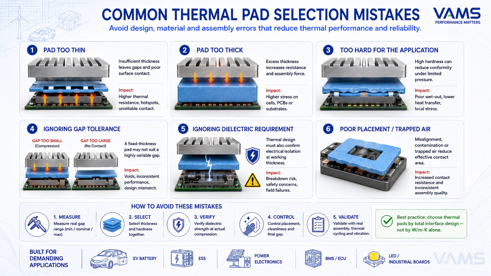
Common selection mistakes: W/m·K-only choice, over-thick pad, over-compression, variable gap, false structural bond.
- Selecting a thermal pad only by W/m·K while ignoring thermal impedance
- Choosing a pad too thick for the actual gap
- Ignoring compression force on battery cells, PCBs or ceramic substrates
- Using a fixed-thickness pad where gap tolerance is too variable
- Treating adhesive-backed pads as structural bonding
- Ignoring liner removal direction, placement tolerance or surface cleanliness
- Not validating compression set, thermal cycling, humidity and vibration
- Overlooking dielectric strength at the actual working thickness and pressure
Why VAMS
- Thermal pad portfolio from soft, low-stress grades to higher-conductivity and reinforced options; UL 94 V-0 options available depending on grade
- Die-cut part design support including geometry, thickness, liner, adhesive side, reinforcement and handling requirements
- Material selection based on gap tolerance, heat load, compression limit, dielectric requirement and assembly process
- Support for thermal impedance targeting, compression design, final gap review and reliability validation
- TDS/SDS and project documentation support for EV, ESS/BESS, e-motor and power electronics customers
- Local sampling coordination and technical support for customers in Vietnam and Southeast Asia
Thermal Interface Materials (TIM)
Thermal Gap Filler for EV Battery Packs
PCB & Power Electronics Material Solutions
Battery System Material Solutions
Need help selecting the right thermal pad?
Tell us your nominal gap, tolerance stack-up, heat load, compression limit, dielectric requirement and assembly process. VAMS can help recommend a suitable thermal pad construction, thickness and grade for your application.