
Thermal Gap Filler for EV Battery Packs
Low-stress dispensable thermal interface for cell-to-cooling-plate heat transfer
Values are typical reference ranges and may vary depending on material grade, bond-line thickness, filler loading, substrate condition, dispensing method, cure profile and validation method.
A battery cell only cools as well as the thermal path between it and the cooling plate. This interface often contains microscopic air gaps that increase thermal resistance. Thermal gap fillers are dispensable, thermally conductive materials designed to fill these gaps with a conformable heat-transfer path while maintaining low assembly stress on cells. This guide covers chemistries, properties and dispensing parameters.
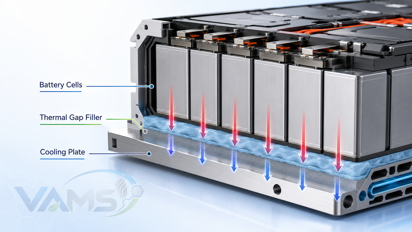
Cells/module bonded to the cooling plate via dispensed gap filler — a continuous heat path
Why Thermal Gap Fillers
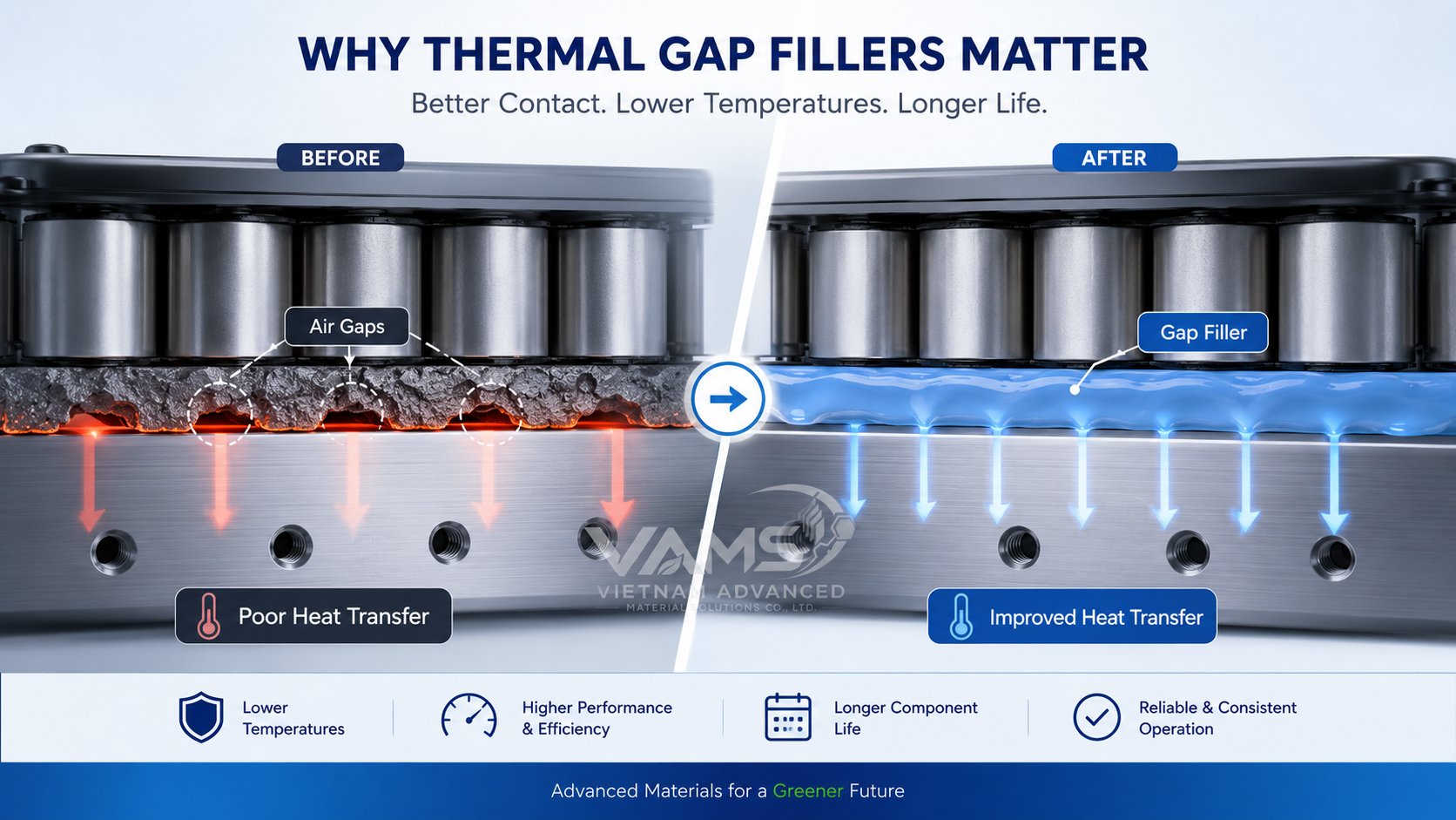
Gap fillers replace insulating air gaps with a conductive, low-stress path to the cooling plate
Cells perform and age best in a tight temperature window (≈20–40°C). The cooling plate removes heat, but only if heat can cross the cell-to-plate interface. Gap fillers replace insulating air with a conductive material, and — unlike rigid pads — flow to fill uneven gaps and large tolerances without high reaction force on the cells.
- Low thermal resistance: conductive path from cell base to cooling plate
- Tolerance absorption: fills variable gaps (often 0.5–3 mm) in one dispense
- Low compression stress: soft, low-stress grades help reduce mechanical load on cells or pouches under defined assembly conditions
- Dielectric isolation: keeps cells electrically isolated from the plate
Types & Chemistry
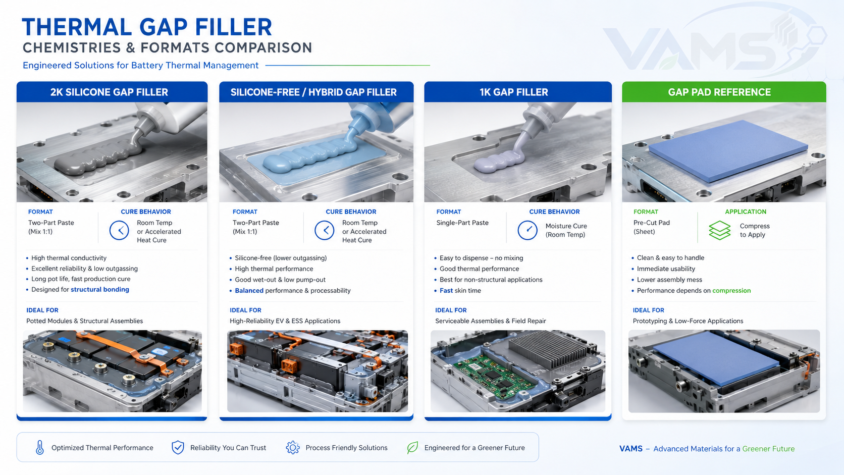
1K/2K silicone and silicone-free dispensable gap fillers, plus pre-cured pad alternatives
| Type | Cure | Notes |
|---|---|---|
| 2K Silicone gap filler | Mix & cure (RT / heat accel.) | Wide temp range, stable, reworkable; most common for packs |
| 2K Silicone-free / PU / epoxy hybrid | Mix & cure | Where silicone is restricted (LABS / contamination concerns) |
| 1K gap filler | Moisture / heat | Simpler dispense; check depth-of-cure for thick beads |
| Pre-cured gap pad (reference) | — | Die-cut alternative for fixed gaps / lower volume |
Typical Properties
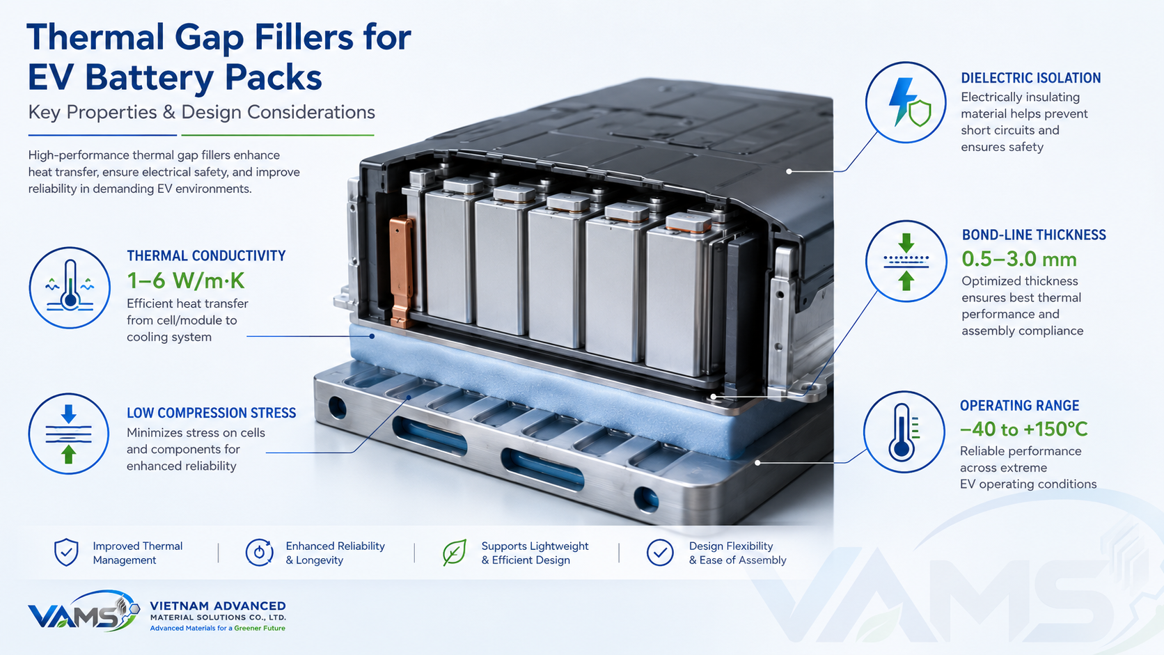
Key properties — thermal conductivity, low compression stress, dielectric isolation and flammability
| Property | Standard / Method | Indicative Value |
|---|---|---|
| Thermal conductivity | ISO 22007 / ASTM D5470 | 1.0–6.0 W/m·K |
| Thermal impedance | ASTM D5470 | Low; decreases with thinner bond line |
| Hardness | Shore 00 | ≈ 40–80 (soft, conformable) |
| Density | — | 2.5–3.5 g/cm³ (filler dependent) |
| Dielectric strength | IEC 60243 | > 10 kV/mm (typical) |
| Volume resistivity | — | ≥ 10¹² Ω·cm (electrically insulating, grade dependent) |
| Flammability | UL 94 | V-0 grades available |
| Operating temperature | — | −40 to +150°C (silicone) |
Higher conductivity needs higher filler loading, which raises density, viscosity and pump abrasion. Specify the real target — over-spec adds cost and mass. Refer to the product TDS for certified values.
Design & Selection
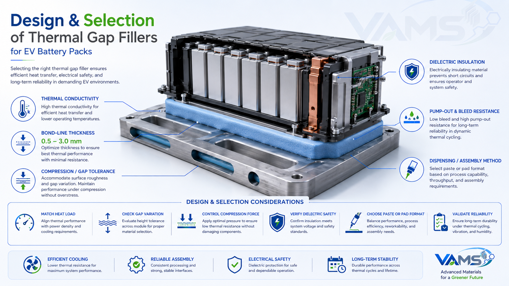
Matching gap filler conductivity, bond-line thickness and stiffness to the pack design
- Match conductivity to heat load: 1–2 W/m·K for light packs; 3–6 W/m·K for high-power/fast-charge
- Minimize bond-line thickness: thermal resistance scales with thickness — design the gap as small as tolerances allow
- Keep cells low-stress: choose soft (low Shore 00) grades to protect cell cans/pouches
- Confirm compatibility: silicone vs. silicone-free per OEM contamination/LABS rules
- Plan for rework: some silicone fillers allow module removal/repair
Dispensed gap filler suits automated, high-volume lines and variable gaps. Pre-cured gap pads suit fixed gaps and lower volumes. VAMS can advise on the right format for your line.
Higher thermal conductivity is not always the best choice. The final selection should balance conductivity, bond-line thickness, viscosity, density, pump wear, compression stress and process stability.
Dispensing & Process
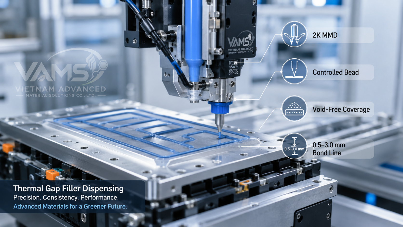
Automated meter-mix dispensing of gap filler onto cells / cooling plate
| Parameter | Typical Window |
|---|---|
| Dispense | 2K meter-mix-dispense (MMD), robotic bead/pattern |
| Mix ratio | 1:1 common (grade dependent) |
| Bond-line thickness | 0.5–3.0 mm typical (design to minimum) |
| Working / cure time | Tunable; RT or heat-accelerated |
| Equipment wear | Abrasive fillers — use hardened wetted parts |
| Quality checks | Wet-out coverage, void-free, bond-line gap verification |
Why VAMS
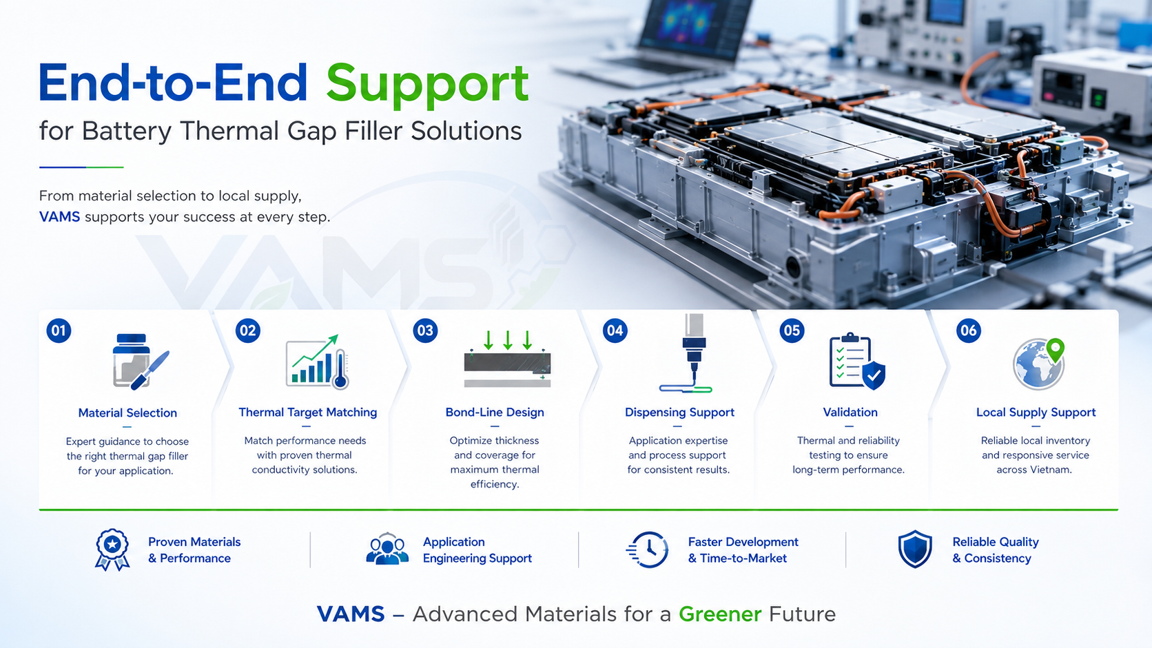
End-to-end support — conductivity targeting, bond-line design, dispensing and supply
- Dispensable 1K/2K thermal gap fillers from 1 to 6 W/m·K, silicone and silicone-free
- Soft, low-stress grades that protect cells while filling large tolerances
- UL 94 V-0 and electrically insulating options available depending on product grade and battery safety requirements
- Process support: conductivity targeting, bond-line design, MMD dispensing, pump-abrasion guidance
- TDS/SDS and project documentation support for PPAP or customer approval; local sampling coordination across Vietnam & Southeast Asia
Thermal Interface Materials (TIM)
Thermal Pads Selection Guide
Battery System Material Solutions
Aerogel & PC Sheet Thermal Barriers
Need help selecting a thermal gap filler?
Tell us your gap range, heat load, dispensing process and dielectric requirement. VAMS can help recommend a suitable gap filler grade and dispensing approach for your application.